Speak to an Air Purification Expert
Speak to an Air Purification Expert
MistBuster® Installation
INSPECTION
The MistBuster® air cleaner should be checked for any shipping damage that may have occurred during shipping. Any damage should be noted, and the carrier notified immediately.
TOOLS & EQUIPMENT REQUIRED
The following is a list of tools that would be needed for typical installations:
- Reciprocating saw
- Drill
- Screwdriver
- Wrenches
- Fork truck / Crane
PLANNING THE INSTALLATION
- The MistBuster® mist collector should be located with consideration for convenience of maintenance and electrical compartment access.
- The filter access door on the MistBuster® should not be obstructed. A minimum of 24” is needed in front of the filter access door.
- The side access covers should also be accessible, if possible. This will make it easier to access the electrical components such as the switches and high voltage power supplies.
- Mount the MistBuster® as far from the chip conveyor opening as possible. This will minimize the amount of clean shop air from being drawn into the enclosure.
DIRECT MOUNT TO MACHINE TOOL ENCLOSURE
The MistBuster® can be mounted directly to the enclosure on a machine tool. The collected mist droplets simply drain back into the machine tool through the air inlet of the MistBuster®.
INSTALLATION DIRECT MOUNT
Remove all filters and electronic cells from the MistBuster®. Carefully position the MistBuster® on the machine tool in the desired location. Refer to Planning the Installation for guidelines in positioning the MistBuster® on the machine tool.
- Use the inlet opening and the mounting hole pattern on the bottom of the MistBuster® as a template to mark the inlet opening and holes to be drilled into the machine tool enclosure. If the machine tool enclosure has been designed with a provision for mist collection, you may not need to cut an inlet opening. NOTE: The inlet opening in the machine tool does not need to be as large as the inlet of the MistBuster®. It is recommended that the inlet opening be a minimum of 30 sq in for MB500, MB850C and MB850, 80 sq in for MB2000.
- Use a .281”[7mm] diameter drill bit to drill the mounting holes for the 1/4-20 bolts used to secure the MistBuster® to the machine tool.
- There are fourteen mounting holes in the MistBuster®. It is recommended that a minimum of four holes to be drilled to secure the MistBuster® to the machine tool.
- The MistBuster® comes complete with a 10’[3048mm] power cord. Plug the unit into the appropriate grounded outlet.
- Replace the impingers and the electronic cell. Please make sure the arrows on the cells and filters are pointing up.

Bottom view of MB500, MB850C and MB850

Bottom view of MB2000
DUCTED INSTALLATION
When direct mounting of MistBuster® is impossible or not desired, the MistBuster® can be installed with a plenum and ducting.
The simplest ducted installation will require our sloped plenum. The plenum has incorporated mounting
legs, one side intake; and it is sloped in two directions to the drain. You can change the intake side by rotating the plenum 180 degrees.

MB500 with 6 in inlet sloped plenum

MB500 with 8 in inlet sloped plenum

MB850C with 6 in inlet sloped plenum

MB850C with 8 in inlet sloped plenum

MB850 with 6 in inlet sloped plenum

MB850 with 8 in inlet sloped plenum

MB2000 with 8 in inlet sloped plenum
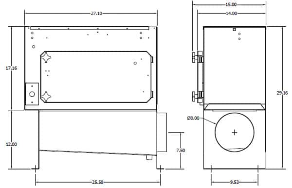
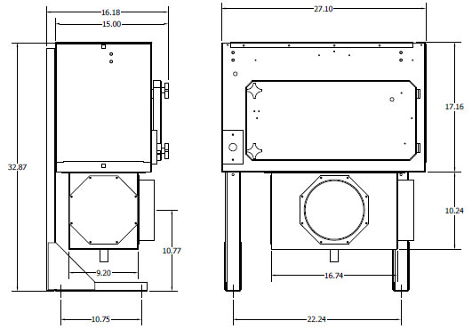
MistBuster® could be installed with machine mount legs and our standard attached plenum. The plenum has holes on three sides and comes standard with two covers and one inlet collar.
Additional ports can be ordered in 4”[102mm], 6”[152mm] and 8”[203mm] diameters.
INSTALLING THE PLENUM
- Install the supplied covers and collar to the plenum using the supplied silicone sealant and #8 screws.
- Attach the plenum to the inlet opening on the MistBuster® using the supplied silicone sealant and 1/4- 20 bolts and nuts. Note that the plenum may be rotated 180° for the desired port orientation.

MB 500 and MB 850

MB 2000
MACHINE MOUNT STAND
- Remove the six bolts on the back of the MistBuster® and install the two L-brackets.
- Carefully drill the required number holes in the machine tool to attach the L-brackets from the
machine mount stand using a 13/32” drill bit for MB500 and 7/16” for MB850 and MB2000. - Use a crane or fork truck to lift the assembled MistBuster® onto the machine tool. CAUTION: Make sure the MistBuster® is secured to the crane or forklift to avoid personal injury or damage to
the unit. Bolt the MistBuster® to the machine tool using the supplied 3/8” nuts, bolts and lock
washers.

MB500 with machine mount legs

MB850C with machine mount legs

MB850 with machine mount legs

MB2000 with machine mount legs

CEILING KIT OPTION SHOWN
CEILING MOUNT
WARNING
The overhead structure must be strong enough to support the weight of the MistBuster®, plenum and ductwork.
Risk of severe injury could result from improper installation.
Make sure that whenever using a fork truck, hoist or lift that the MistBuster® is properly secured to prevent tipping.
Use caution not to damage the MistBuster® or plenum with the fork truck, hoist or lift.
- Attach the four angle brackets to the front and back of the MistBuster® using the eight supplied bolts and lock washers. Fasten the four 3/8” eyebolts to the four brackets using the supplied hardware.
- Install the supplied covers and collar to the plenum using the supplied silicone sealant and #8 screws. Attach the plenum to the inlet opening on the MistBuster® using the supplied silicone sealant and 1/4- 20 bolts and nuts. Note that the plenum may be rotated 180° for the desired port orientation.
- Install the MistBuster® using cable or chain to suspend the unit from each eyebolt. Make sure that
the cable or chain is rated for the appropriate weight of the MistBuster® and accessories. Position
the chains or cables so that they form a 60° angle with the top of the unit and a 45° angle from the
side surfaces. This will make the unit more stable. - Level the MistBuster® in all directions.
PEDESTAL STAND INSTALLATION
WARNING
The pedestal stand must be anchored to the floor before it is assembled to the MistBuster® to prevent tipping.
Do not extend the top of the stand over 128”[3251mm].
Level the stand before securing the anchor bolts.
- Slide the upper part (T-section) of the pedestal stand into the lower section (lower section contains the base which bolts to the floor).
- Secure the base of the pedestal stand to the floor using four 1/2” anchor bolts (not supplied). Anchor bolts must be secured before the MistBuster® is assembled to the stand. Anchor bolts must extend 1 1/2” above the floor to ensure adequate length.
- Assemble the upper and lower pieces together by inserting the four 3/8-16 x 3.5”[90mm] long bolts through the flat washers, lower section of the stand and lock washers as pictured below. To adjust the height of the pedestal stand, loosen the four 3/8-16 x 3.5”[90mm] long bolts from the lower part of the stand and slide the upper section of the desired height. Do not adjust the top of the stand over 120” [3251mm] high. Tighten the bolts to create enough tension to secure the stand in place.
- Remove the bolts and lock washers from the back of the MistBuster®. Remove the electronic cell and impingers from the MistBuster® and lift the unit up to the pedestal stand. Align the MistBuster® and insert and tighten the bolts with lock washers to secure the MistBuster® to the pedestal stand. Install the plenum per the instructions in the Installing the Plenum section.
- Re-check all bolts to make sure they are securely fastened.
DRAIN INSTALLATION
The MistBuster® plenum has a 1/2” female pipe fitting drain that requires a P-trap and a drain hose to
return the metalworking fluid to the machine tool.
Prime the P-trap with the metalworking fluid that will be collected to avoid air being drawn through the plenum drain.


